Diodes
The image below shows how a diode can be modeled as a simple voltage source or as a voltage source and a resistor to approximate its real behavior.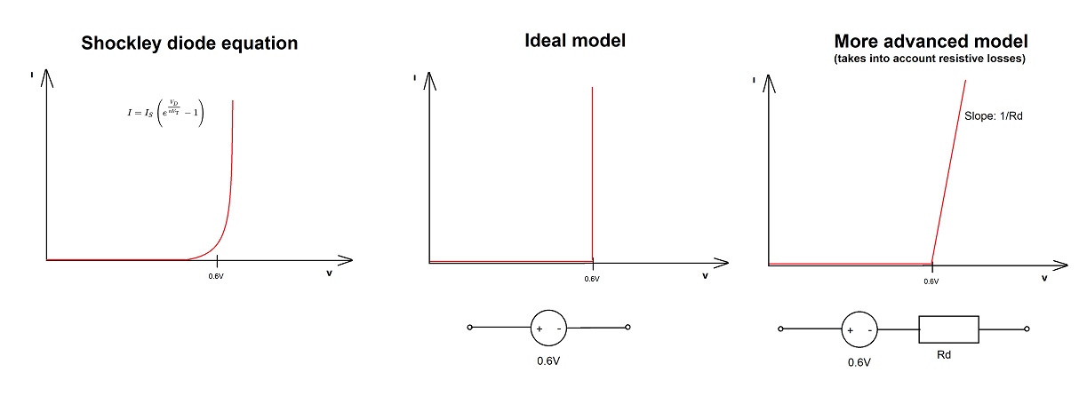
Devices like diodes and transistors are non-linear devices. This means that the mathematics to solve them can become very complex. Solving circuits with these elements is often done by using computer simulation software (i.e. SPICE).
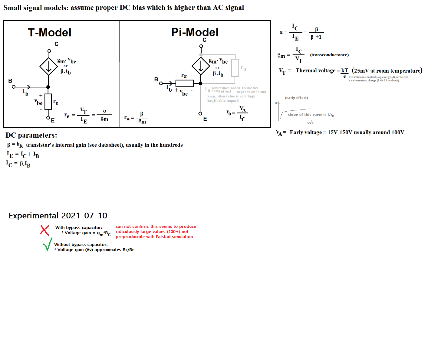
In order to be able to analyse circuits containing transistors, models have been developed that replace them with a number of linear components, like resistors, voltage and current sources, capacitors and inductors. This allows approximating the behaviour of the transistor while still only utilizing easy to solve linear components. Depending on the type of circuit one of several models can be chosen to work with. Most models can be used in a simplified or extended version to account for more advanced concepts such as the Early effect and Miller effect. In many cases these effects do not have a substantial impact on the behaviour of the circuit and can be safely removed from the model, thus making the circuit a lot more easy to solve.
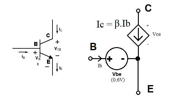
Vbe being set to either 0.6V or 0.7V. This is likely
based on the perspective of the teacher. For circuits where a relatively high base current is common
a higher value is probably assumed compared to applications witch usually employ lower currents. In some
practical amplifier circuits I have studied, the base current is often just a few micro amps, and actual
values of Vbe are just shy of 600mV.
TODO: add models for other transistor modes (saturation and cutoff) + explain how to determine
For AC circuit analysis, there are different models available. Both models presented here are simplified. That is they are not for very high frequency analysis, where parasitic capacitances and special physical effects of the transistor come in to play.
The models here as so called small signal models, which means that they assume the transistor is operating on a DC bias point that is properly setup and is much higher than the AC signal that is in superposition on top of the DC bias. For amplifier circuits this is the case.
However, for normal usage, they are quite accurate. Most circuit theory I have seen utilize these simplified models, and I have used them to successfully predict real world circuit behaviour with success.